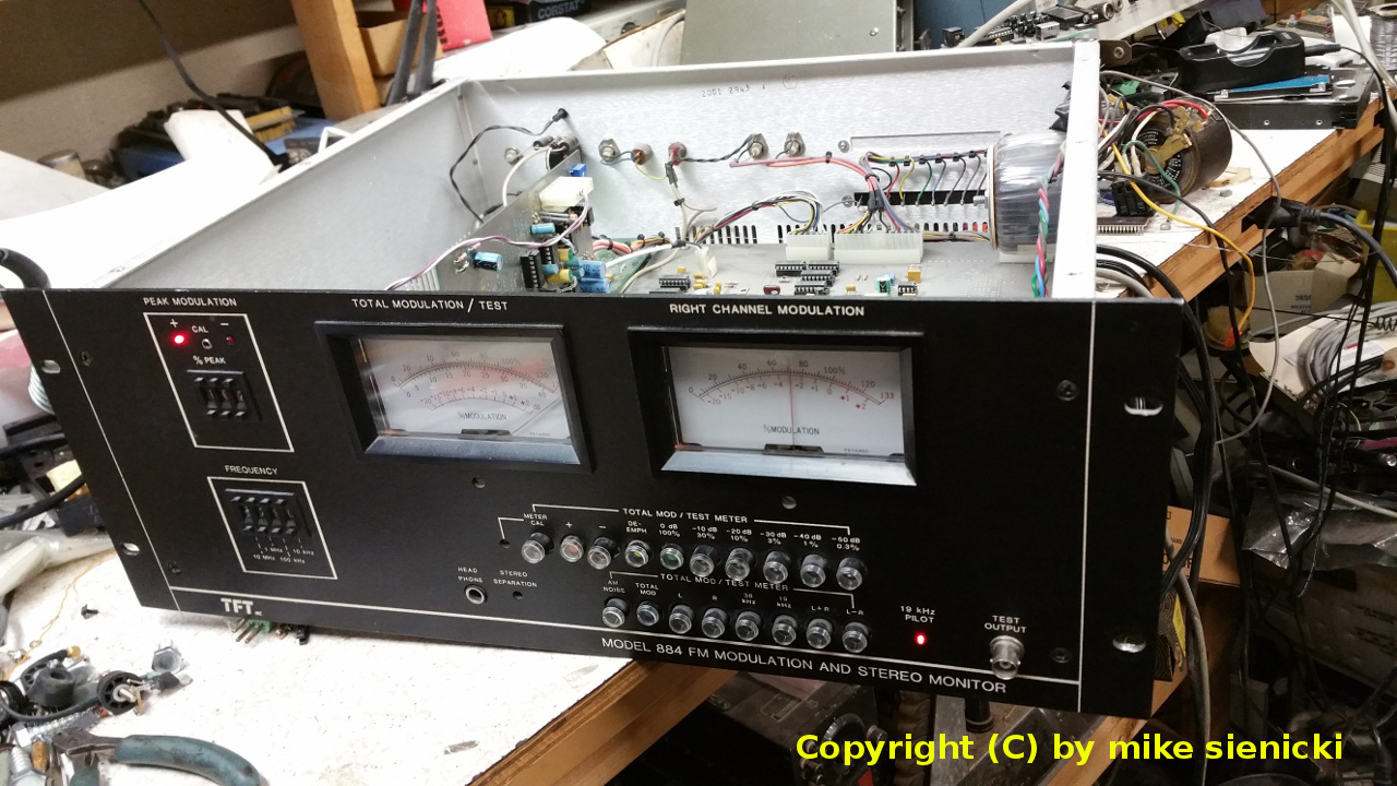
Taming the TFT Model 884 FM
Modulation Monitor
|
|
|
|
There appears to be an ugly
intermittent that was designed into this unit that can
not only be frustrating for the engineer that relies
upon it to help keep the station in compliance with
FCC rules, but, also frustrating to the on-air staff
that uses it to externally monitor their
product. If your 884 is intermittent in
operation then it's very likely that the below
modification will solve this. Since most radio
stations are on a tight budget the best option is
probably to repair your monitor versus buying a new
costly one.
|
|
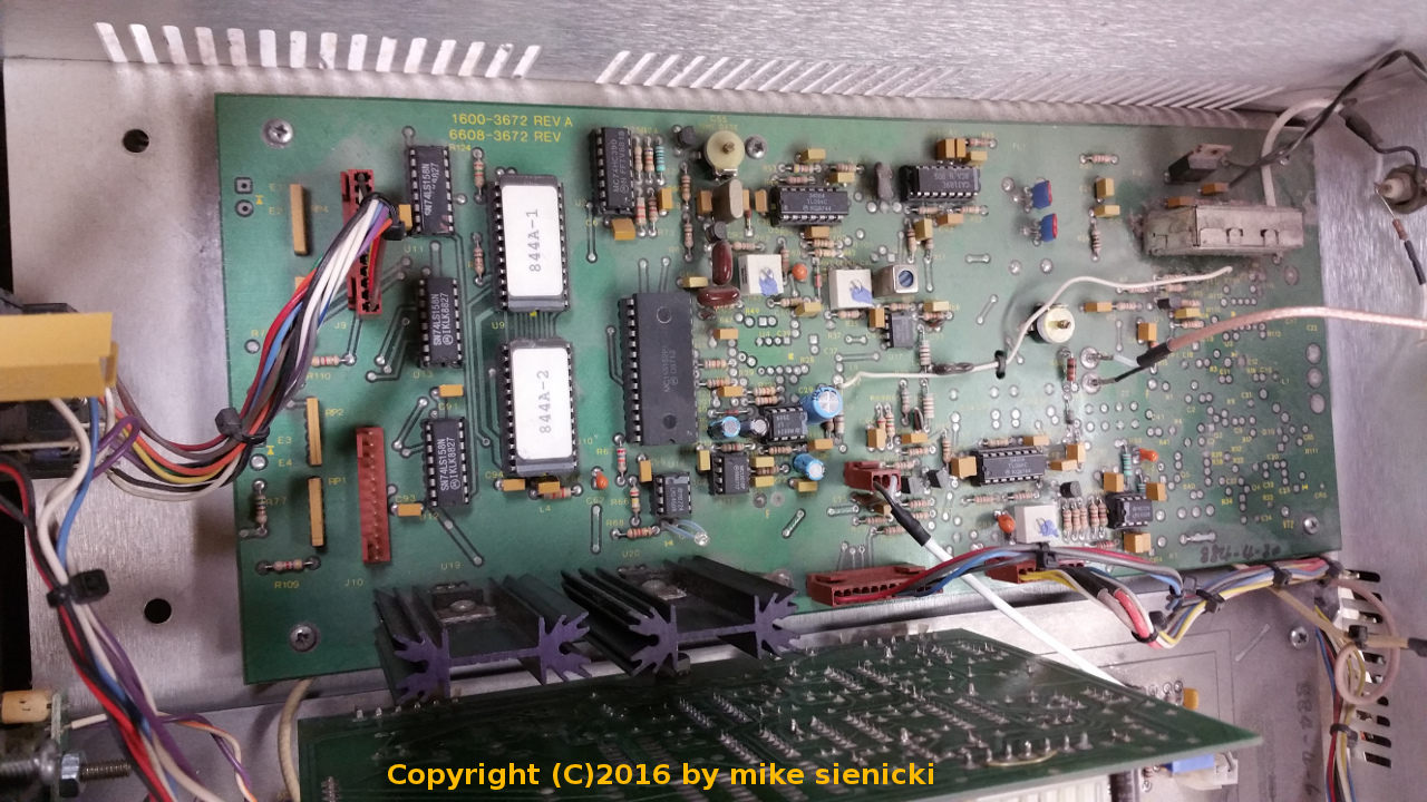
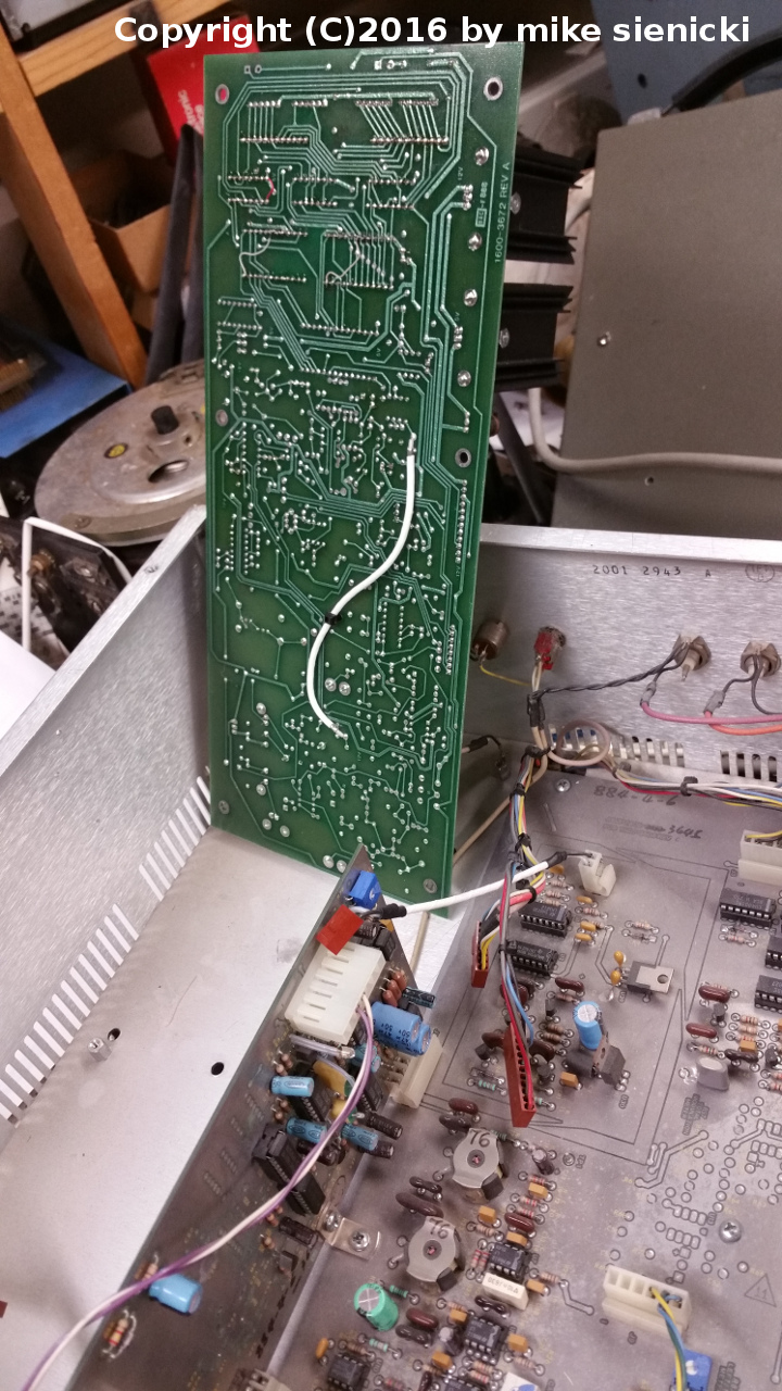
The illustration below is a view of
the circuit board (PWA) that requires this modification
and is held in by only six screws. Carefully
remove the screws and four Molex connectors. There
is one coaxial cable that is soldered to the circuit
board that shouldn't be a problem for you if you lift
the front edge of the board upwards and to the rear of
the 884. The last illustration on this page shows
this.
|
 |
|
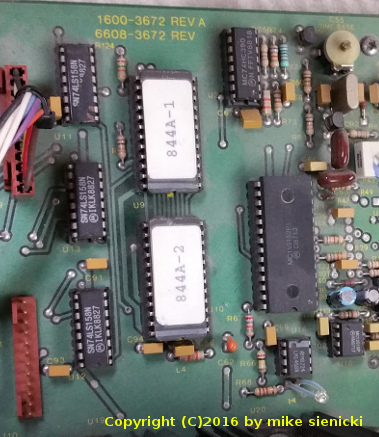
The frequency
synthesizer IC (a Motorola MC145152) divider chain is
loaded by data that is fed from two CMOS 27C32 EPROM's
depending on how their address lines are set up by the
frequency selection thumbwheel switches located on the
front panel. It was discovered that the designer/s left
three crucial inputs to these devices unconnected (as in
floating)! These EPROM's are shown in the illustration
below and are labeled 844A-1 and 844A-2.
|
|
|
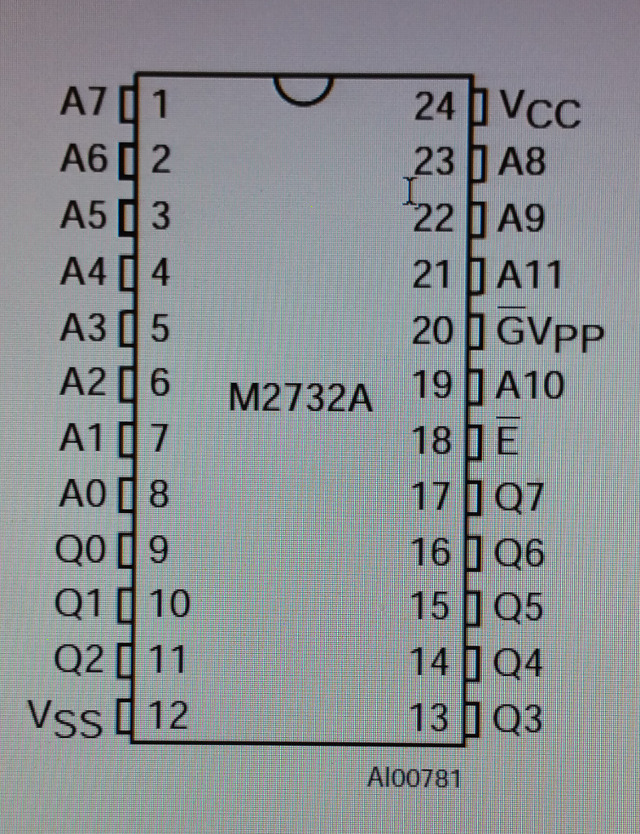
Further investigation reveals that as long as pin numbers
18, 19, and 20 are held at a logic low the monitor
operates normally. Touching the probe of an high
impedance DC voltmeter to any of these three pins will
show that the voltage is unsteady or floating. It's pretty
important that any unused input pins of a CMOS device are
tied to either ground or +Vdd or you can end up with
illogical logic. Note that the pinout diagram for the
EPROMs illustrated below shows these three pins to be the
Enable line, Address 10 line, and the G bar (select) line!
It's no wonder the unit took time off whenever it felt
like it.
|
|
|
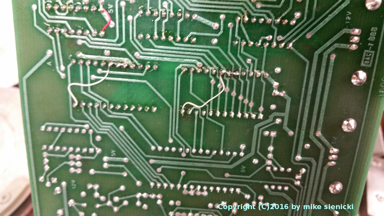
At this point it was
time to get out the soldering station and wire wrap to get
these inputs tied to ground. As you can see I didn't
do the prettiest job, but, as long as care is taken to
leave some space between the circuit traces that run below
the wire wrap lead (illustrated below) then everything
should be fine and no short circuits will result. Note
that this must be done to both EPROMs. Pins 18, 19, and 20
get tied to pin 12 (ground) of each EPROM. Also note that
the red jumper at the top left corner was already there
before I even disassembled the unit. All in all this
turned out to be a fairly simple job.
|
|
|
Wider view of the
modified circuit board (PWA) as illustrated below.
|
|
Reinstall the PWA and
verify the operation of the modulation monitor by
connecting an antenna to the low level RF input, selecting
a strong local station, and listen with a pair of stereo
headphones. With the top cover is still off, it's a good
idea to check all power supplies for ripple and ascertain
that all regulators are giving you the correct voltages. I
found +12V, -12V, +5V, and +8V regulators in various
locations on two of the circuit boards. The final thing I
checked was to turn the whole thing upside down with the
top cover off to see if there was anything loose inside.
Sure enough a small screw fell out. This can happen
because small objects can inadvertently fall through the
vent holes in the top cover of the unit's enclosure over
time.
|
|
|
|
|
|